The support has moved to https://pira.cz/forum/
hevyhomie wrote: Hello, Great Software. Thanks for making it free Thanks, hevyhomie hevyhomie wrote: Hello, Great Software. Thanks for making it free Thanks, hevyhomie admin wrote: Standard PC is not equipped by any hardware controller that allows direct reading of RDS data from the Si4703. However this can be done via Arduino which can translate the data from the Si4703 bus to a simple serial data readable by PC. More information gives the Si4703 datasheet: My recommendation: It is also important to note that Si4703 uses frequency information from the 19 kHz stereo pilot to recover the 57 kHz RDS/RBDS signal. Compared to receivers with full-featured RDS decoders, the Si4703 will probably have very poor RDS performance on stations without pilot tone (mono) or if pilot and RDS are not in phase relation (missing synchronization on the transmitter side). admin wrote: Standard PC is not equipped by any hardware controller that allows direct reading of RDS data from the Si4703. However this can be done via Arduino which can translate the data from the Si4703 bus to a simple serial data readable by PC. More information gives the Si4703 datasheet: My recommendation: It is also important to note that Si4703 uses frequency information from the 19 kHz stereo pilot to recover the 57 kHz RDS/RBDS signal. Compared to receivers with full-featured RDS decoders, the Si4703 will probably have very poor RDS performance on stations without pilot tone (mono) or if pilot and RDS are not in phase relation (missing synchronization on the transmitter side).Si4703 Arduino
Old Forum
(@post)240 PostsRDS Spy forum members

Since I am new here I would like to ask a few questions.
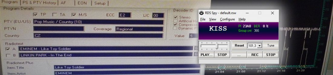
Will RDS Spy work with Si4703 RDS tuners connected to an Arduino Uno R3?
Where can I learn more about RDS programming or encoding/decoding The various groups and group types? Are there always going to be 104 bits streamed broken into 4 blocks of 26 bits (16 bit being the data and 10 bits being the error detection bits) for all receivers using RDS?
Since I am new here I would like to ask a few questions.
Will RDS Spy work with Si4703 RDS tuners connected to an Arduino Uno R3?
Where can I learn more about RDS programming or encoding/decoding The various groups and group types? Are there always going to be 104 bits streamed broken into 4 blocks of 26 bits (16 bit being the data and 10 bits being the error detection bits) for all receivers using RDS? Old Forum
(@post)240 PostsRDS Spy forum members
The Si4703 implements an RDS/RBDS processor for symbol decoding, block synchronization, error
detection, and error correction. RDS functionality is enabled by setting the RDS bit. The device offers two RDS modes, a standard mode and a verbose mode. The primary difference is increased visibility to RDS block-error levels and synchronization status with verbose mode.
Setting the RDS mode (RDSM) bit low places the device in standard RDS mode (default). The device will set the RDS ready (RDSR) bit for a minimum of 40 ms when a valid RDS group has been received. Setting the RDS interrupt enable (RDSIEN) bit and GPIO2[1:0] = 01 will configure GPIO2 to pulse low for a minimum of 5 ms when a valid RDS group has been received. If an invalid group is received, RDSR will not be set and GPIO2 will not pulse low. In standard mode RDS synchronization (RDSS) and block error rate A, B, C and D (BLERA, BLERB, BLERC, and BLERD) are unused and will read 0. This mode is backward compatible with earlier firmware revisions.
Setting the RDS mode bit high places the device in RDS verbose mode. The device sets RDSS high when synchronized and low when synchronization is lost. If the device is synchronized, RDS ready (RDSR) will be set for a minimum of 40 ms when a RDS group has been received. Setting the RDS interrupt enable (RDSIEN) bit and GPIO2[1:0] = 01 will configure GPIO2 to pulse low for a minimum of 5 ms if the device is synchronized and an RDS group has been received. BLERA, BLERB, BLERC and BLERD provide block-error levels for the RDS group. The number of bit errors in each block within the group is encoded as follows: 00 = no errors, 01 = one to two errors, 10 = three to five errors, 11 = six or more errors. Six or more errors in a block indicate the block is uncorrectable and should not be used.
Standard mode should not be used at all. It is not well implemented in the device. Its sensitivity is low because this mode provides only completely well received (or corrected) RDS groups. There's no way how to detect if correction has occurred. For common operation all corrected blocks (1 error or more) should be discarded. RDS correction mechanism can repair some received blocks but it also increases a number of nonsensical blocks. It is usually much bigger problem to receive nonsense data than leaving some data missing.
The Arduino should wait for the new group ready event, read the RDSx registers and read the BLERx registers. The RDSx registers can be converted directly to ASCII HEX (see the ASCII G protocol specification in the RDS Spy manual). Where BLERx indicates error, appropriate block should be replaced by '- – – -' in the HEX string. Finally, the group can be sent to PC and RDS Spy.